When Floppy Drives Fail to Eject Disks
How to Replace a Broken Eject Mechanism Gear
by Roger Gibby, May 1, 2016
Your 800K floppy drive has suddenly stopped ejecting disks. You could stop using the drive and get an external drive off eBay. There are alternatives for those who are adventurous and mechanically inclined. There are a few reasons why a disk may fail to eject, but the most likely reason is the plastic gear in the eject mechanism. After thirty years, this gear in the eject mechanism can become brittle and is prone to breaking apart.
Replacing the gear is a simple operation. Of course internal floppy drives are more involved, as one would need to open the Macintosh case, being mindful of the CRT, which can still carry high voltage, even after being unplugged. You shouldn't take opening a vintage Mac lightly.
In this walkthrough, I will be replacing the gear in the eject mechanism of an external drive.
- Open the case and disconnect the interface cable.
- Remove the drive from the metal cage.
- Remove the eject mechanism from the drive.
- Remove the eject mechanism cover.
- Replace the gear.
- Put it all back together
- Put the cover plate back in place
- Reattach the eject module to the drive.
- Slide the drive back into the cage and reattach to the cage
- Plug cable into the back of the drive. Reattach the cable to the cage, if it was removed, during disassembly.
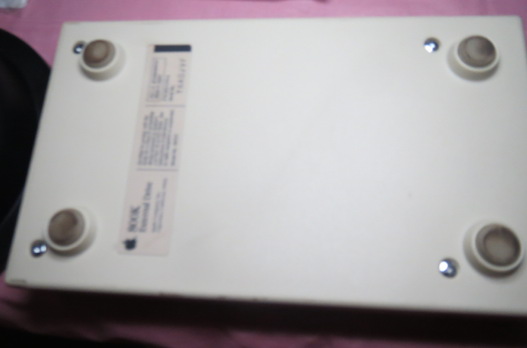
Turn the drive over and remove the four screws on the bottom of the case. Lift off the bottom case to reveal the drive in its cage mounted to the top case. Before removing the screws holding the cage to the case, disconnect the cable from the rear of the drive. Optionally, remove the cable from the cage. There are two screws holding the cage to the rear of the case, by the cable connector. The front of the cage is held into place by two plastic tabs that the cage slides into. After removing the two screws, lift from the back of the cage and slide the cage out from the slots.
There are four screws, two on each side, holding the drive stationary in the cage. Remove all four screws and slide the drive out of the cage, taking care to not touch the drive head/pressure pad. Any pressure on this could render the drive inoperable. When sliding the drive out of the cage hold the drive on the sides.

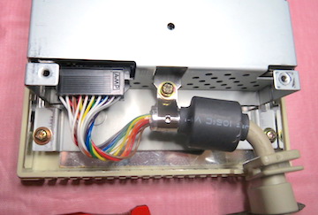
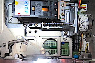
The rectangular black piece in the middle of the above photo is the read/write mechanism. Avoid making any contact with this. If you slid the drive out in the same direction that is depicted in the picture, the eject module will be in the upper left, away from you. If needed, orient the drive so the eject module is on the lower right, next to you. This will make it easier to remove.
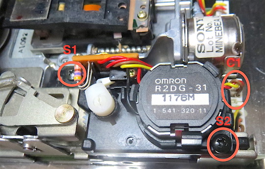
There are two screws that hold the mechanism in place on the drive (red circles labeled S1 and S2 on the top-left and bottom-right. There is also a connector cable that needs to be unplugged (red circle labeled C1 on the top-right).
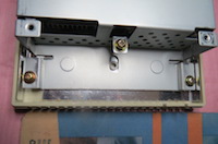
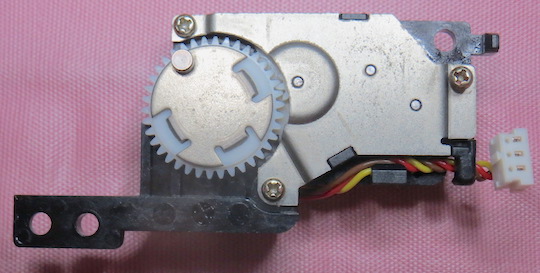
The picture on the right shows how the drive looks with the eject module removed. The cover metal plate is on the other side of the eject module, so turn it over.
There are three screws that hold the cover in place. Remove those screws and pull the cover off. Inside there should be three gears. The yellowish looking gear on the far right is the culprit that has become brittle and is breaking apart. Several of the teeth have broken off. This is the one we are going to replace.
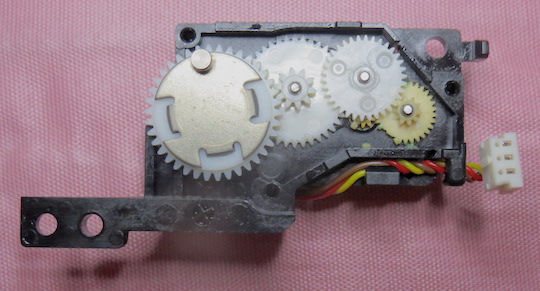
You will need to buy a replacement gear. The gears are nearly impossible to find, but there are people who are making them with 3D printers. I bought mine from a person on eBay. To replace the gear, first remove the middle gear that is sitting over the one we rant to replace. After removing both gears, remove any broken pieces that are in the eject mechanism box.
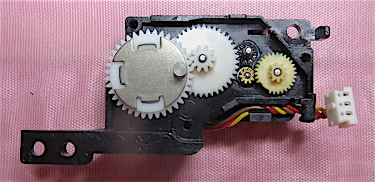
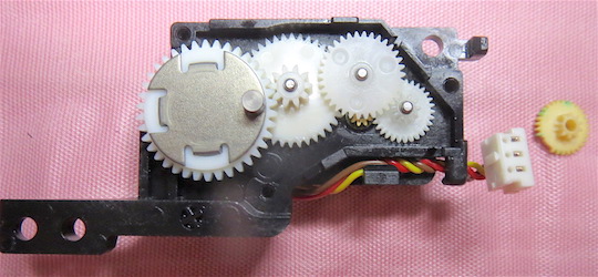
The photo on the right has the broken gear replaced with the new gear.
With the gear replaced, we are ready to put it all back together. We simply do everything in the reverse order.
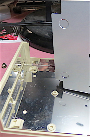
The left photo above shows the tabs on the under side of the case top. The squared out notches on the cage slide into the plastic tabs on the case. If the screw holes do not line up, then it is not sitting in notches correctly. Once the holes line up, reattach the cage to the case with the two screws.
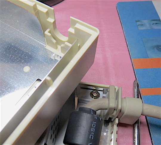
The photo on the right shows the inside of the case with the fitting that lock the cable in place. The outer edge of the case fits Into the outer groove on the cable, The picture is showing the case edge sitting in the groove on the cable. The slots on the inside the case slides into the large slot on the cable, locking the two together. It is a snug fit, so don't be afraid to use a little pressure here. The case will only fit together one way, so if it feels like it won't close together, reexamine how you are putting the case halves together. Do not put the case outer cover into the slot on the cable. It goes in the outer groove.
© 2016 by Roger Gibby. Apple logo is trademarked by Apple Inc.