Apple has a reputation for innovation and one innovation was having an easy way to open and upgrade Mac tower computers. One side of the G3 B&W towers was on a hinge that swung downwards, to lay flat, affording easy access to the RAM, expansion slots and drives.
The Macintosh Pro computers capitalized on the case innovation started with the Blue and White G3 towers. The aluminum cases of the Mac Pro towers had a locking removable side. The modular layout gave easy access to drives and memory.
Mac Pros were powerhouse servers that sported four drive bays, eight RAM slots and two duo core Intel processors. There were a few models that followed with the same architecture, with faster processors. This allowed owners of the early Mac Pro towers to upgrade the processors to two quad core processors.
I recently acquired a Mac Pro Quad Core (two Duo Core 2.66 GHz Xeon 5130 processors). I added two 2GB HD drives and maxed out the memory at 32 GB. These were the easy upgrades. A processor upgrade is a little more involved, but it would give the Mac Pro a tremendous boost, upgrading to two 3 GHz quad core Xeon 5365 processors. I was able to get a pair of processors for less than $100.
|
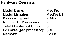
Mac Pro specifications before upgrade:
 |
Preparation
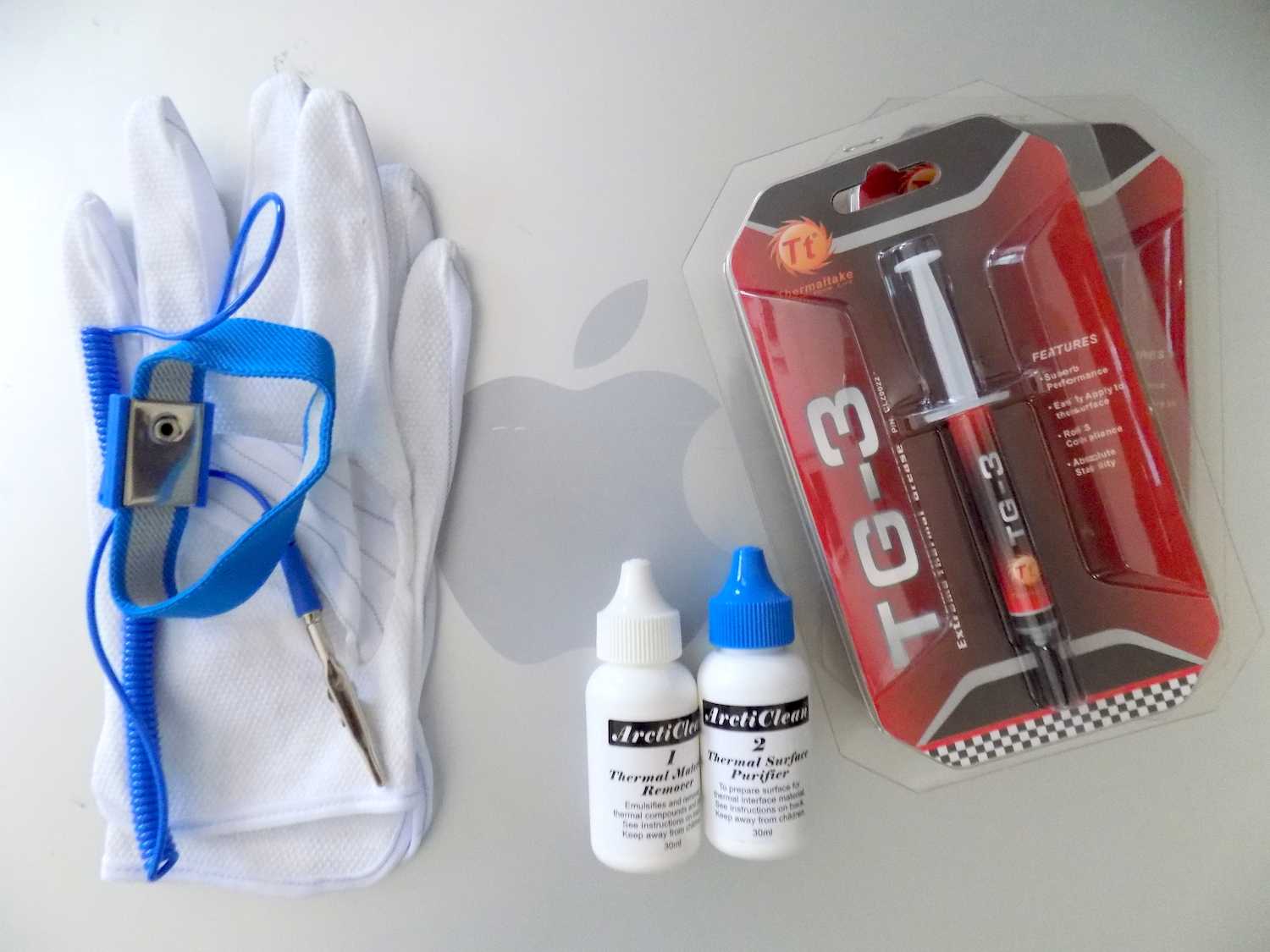
Before attempting to replace the processors in the Mac Pro, there are some items that are needed:
- Anti-static gloves or grounding wrist strap
- Thermal material remover / Surface purifier
- Thermal grease
When handling computer equipment, it is best to protect against damaging the electronics with static electricity. Anti-static gloves are fairly inexpensive and grounding wrist straps are often packaged with repair toolsets. Speaking of toolsets, iFixit makes a nice line of toolkits. I purchased the Classic Pro Tech Toolkit.
The old thermal grease residue will be left on the processor and the heat sink thermal surface. Cleaning fluid is needed to remove the residue from the heat sink. You can buy an ArctiClean package containing the grease remover and surface purifier at an electronics store.
Thermal grease facilitates an effective transfer of heat from the processor to the heat sink. The thermal grease will be applied to the new processor, before putting the hink sink back into place. It usually is available in a squeezable packet or in a syringe. There are two processors in the Mac Pro, so two applicators will be needed; one for each processor.
All of the screws, except for the one's holding the heat sinks in place, are Phillips screws. The screws on the heat sink are Torx screws (T-15). Since the heat sinks are screwed on tightly, I would suggest using a proper Torx screwdriver, instead of using a flathead or some other screwdriver, to save money. It is best to have the right tools for the right job.
Getting to the Heat Sinks
- Remove the side panel
- Remove the left two hard drives
- Remove the memory boards and loosen the memory cage
- Remove the Heat Sink cover
- Remove the front fan assembly
- Remove the plastic divider from the memory cage
- Remove the heat sinks
- Clean parts and computer of dust
- Prepare the heat sinks
- Swap the CPUs
- Put the heat sinks back in place
- The plasic divider in the memory cage
- The front fan assembly
- The heat sink cover
- Secure the memory cage
- Reinstall the hard drives
- Slide the hard drives back into the first two drive bays
- Put the side panel in place and locked
- Sit the Mac Pro upright, plug it in and attach a keyboard, mouse and monitor.
Lay the Mac down on its left side, with the front on the left, the back on the right and the removable panel on top. The latch to unlock the panel is located in the back. Lift up the latch and lift off the panel from the top.
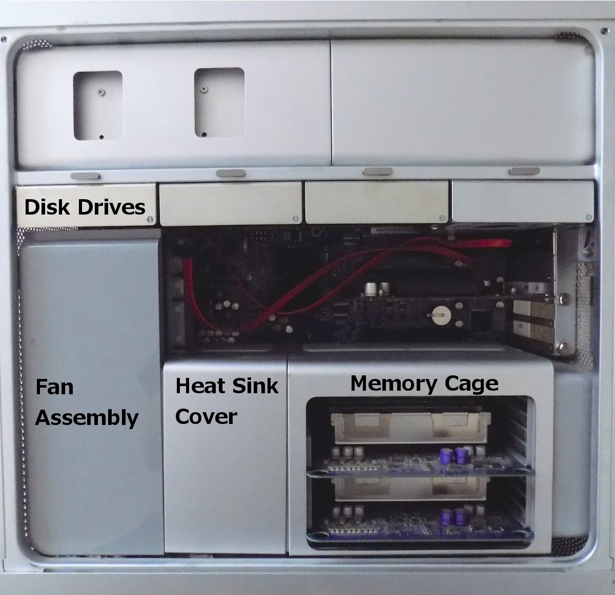
To gain access to the heat sinks and processors, several modules need to be removed: disk drives, memory, heat sink cover and the the fan assembly.
The hard drives are mounted on sleds that are removed, by pulling the sled forward.
There are two slots for memory boards. Remove each of the cards, by grasping the board by the two finger holes in the board.
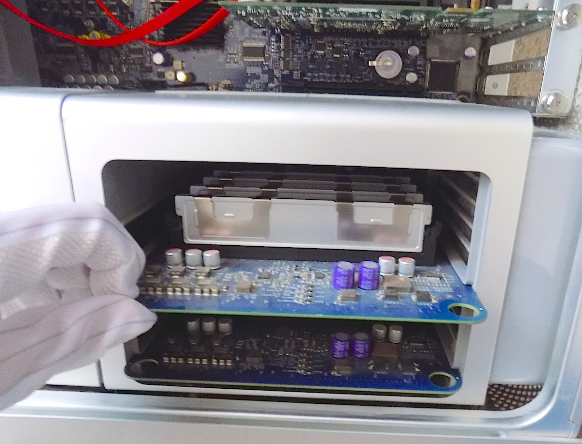
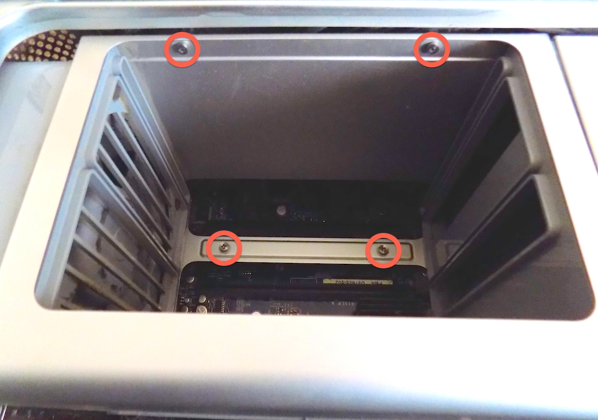
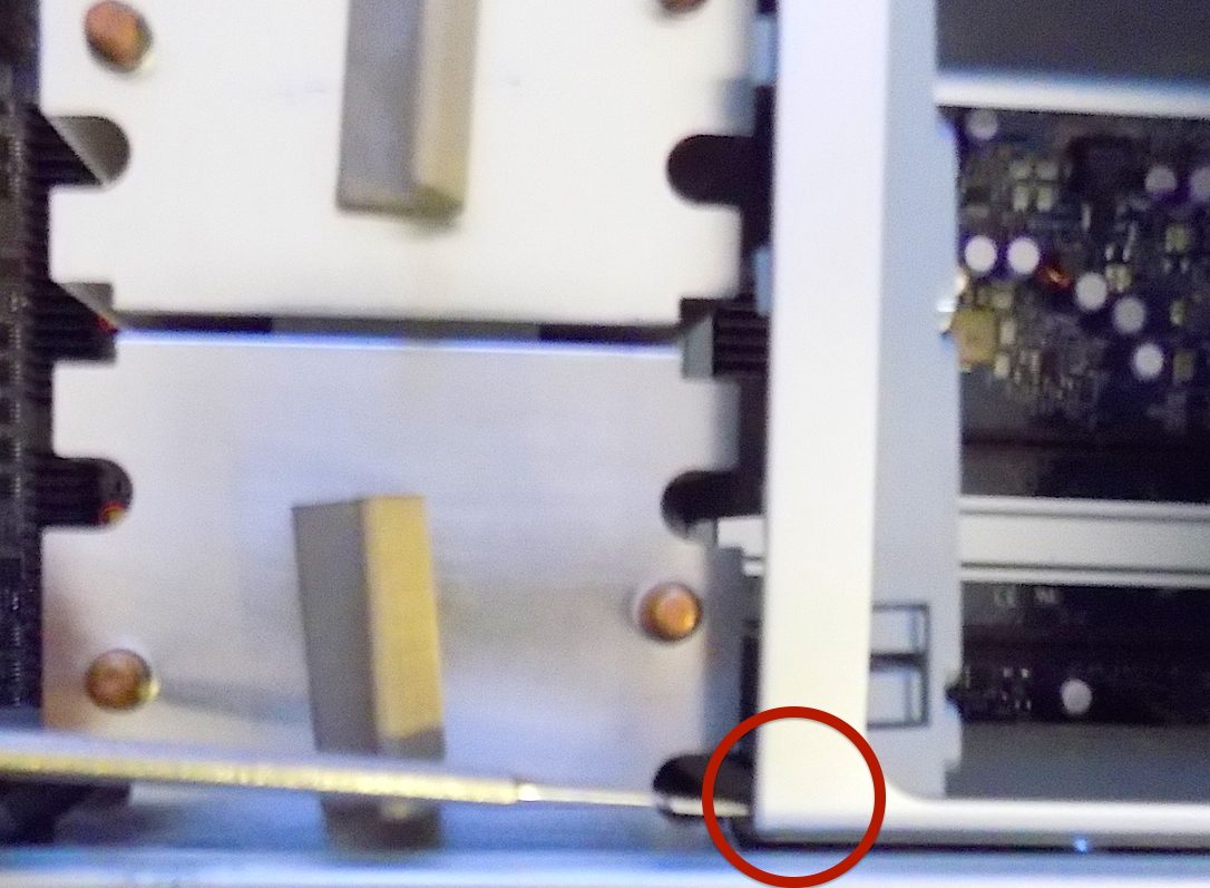
After the memory boards are removed, the memory cage box needs to be loosened, in order to shift the cage to the right enough to slip out the heat sink cover. Remove the four screws circled in red.
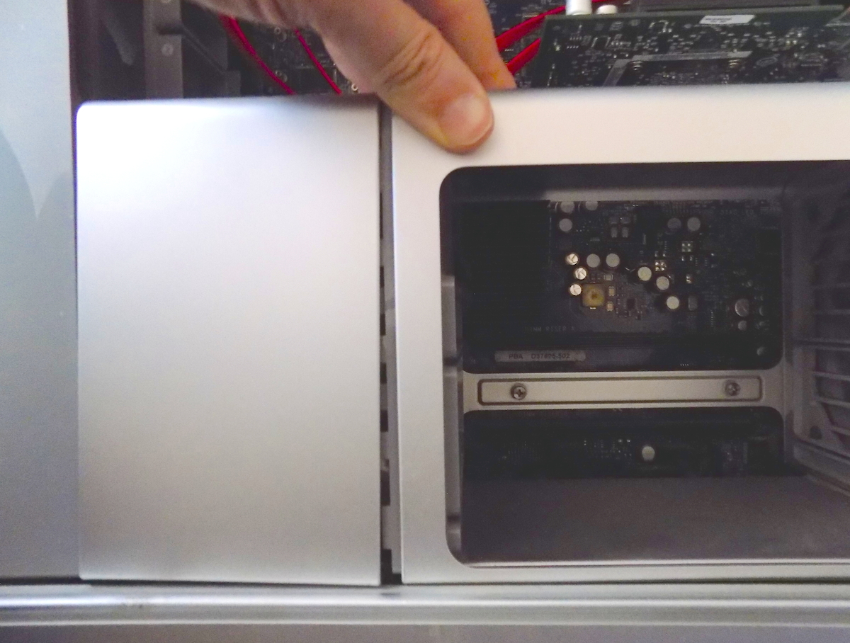
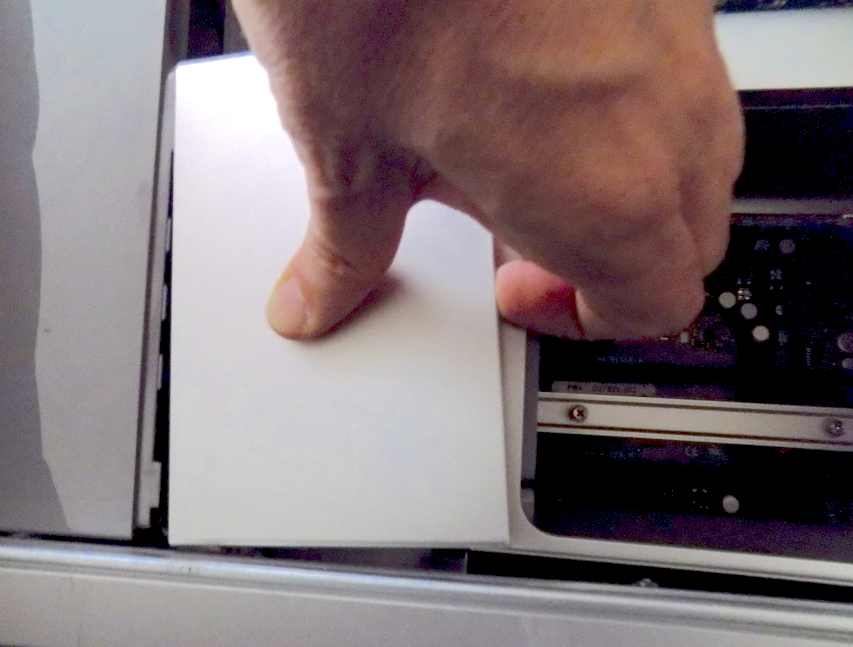
Wiggle the memory cage to the right to free the interlocking tabs on the heat sink cover. Carefully lift off the 'L' shaped cover. Under the cover are two large heat sinks.
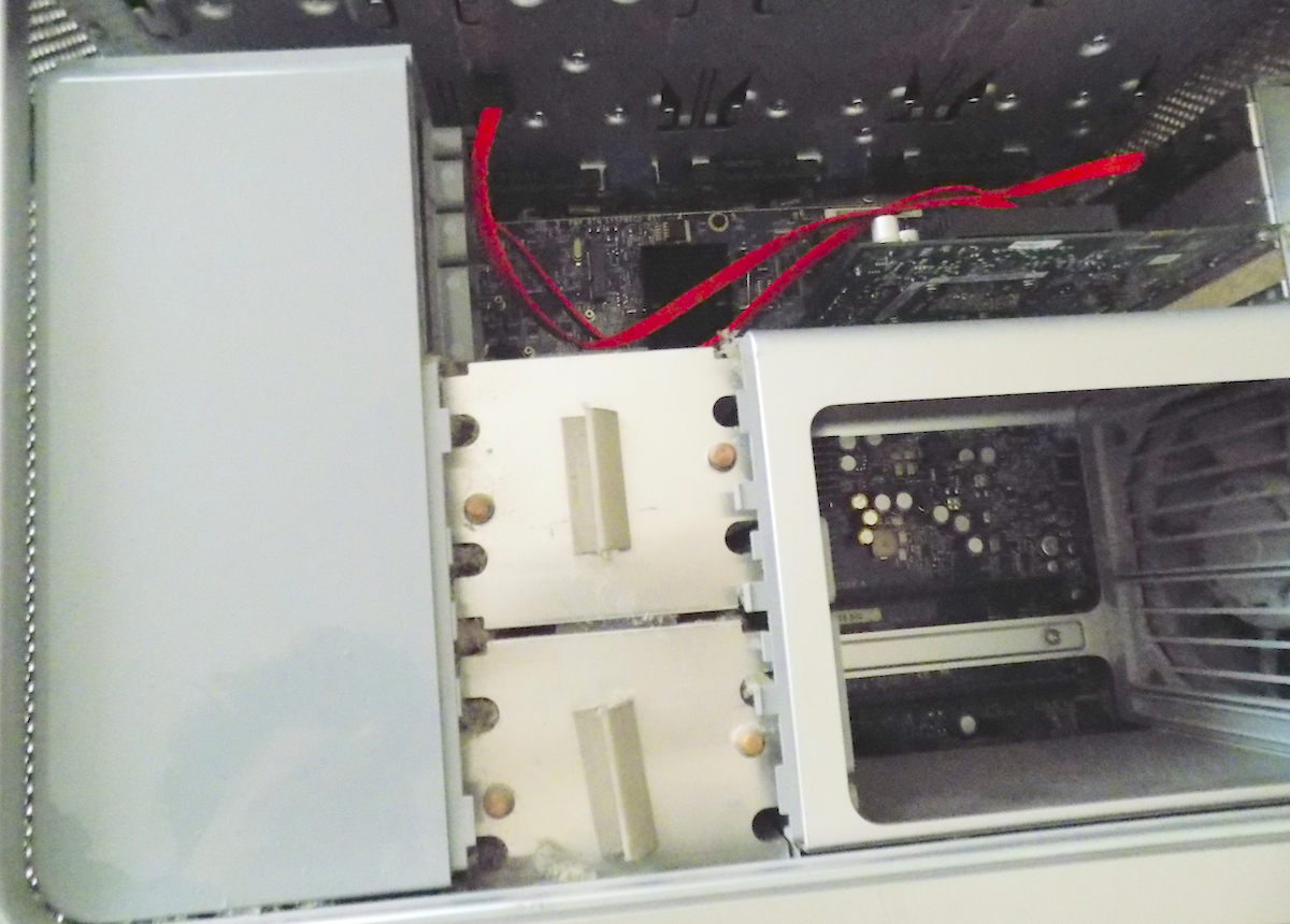
In the picture of the uncovered heat sinks, plastic locking pieces on the fan assembly and the memory cage obstuct removing the heat sinks. Both of these need to be removed before the heat sinks can be removed.
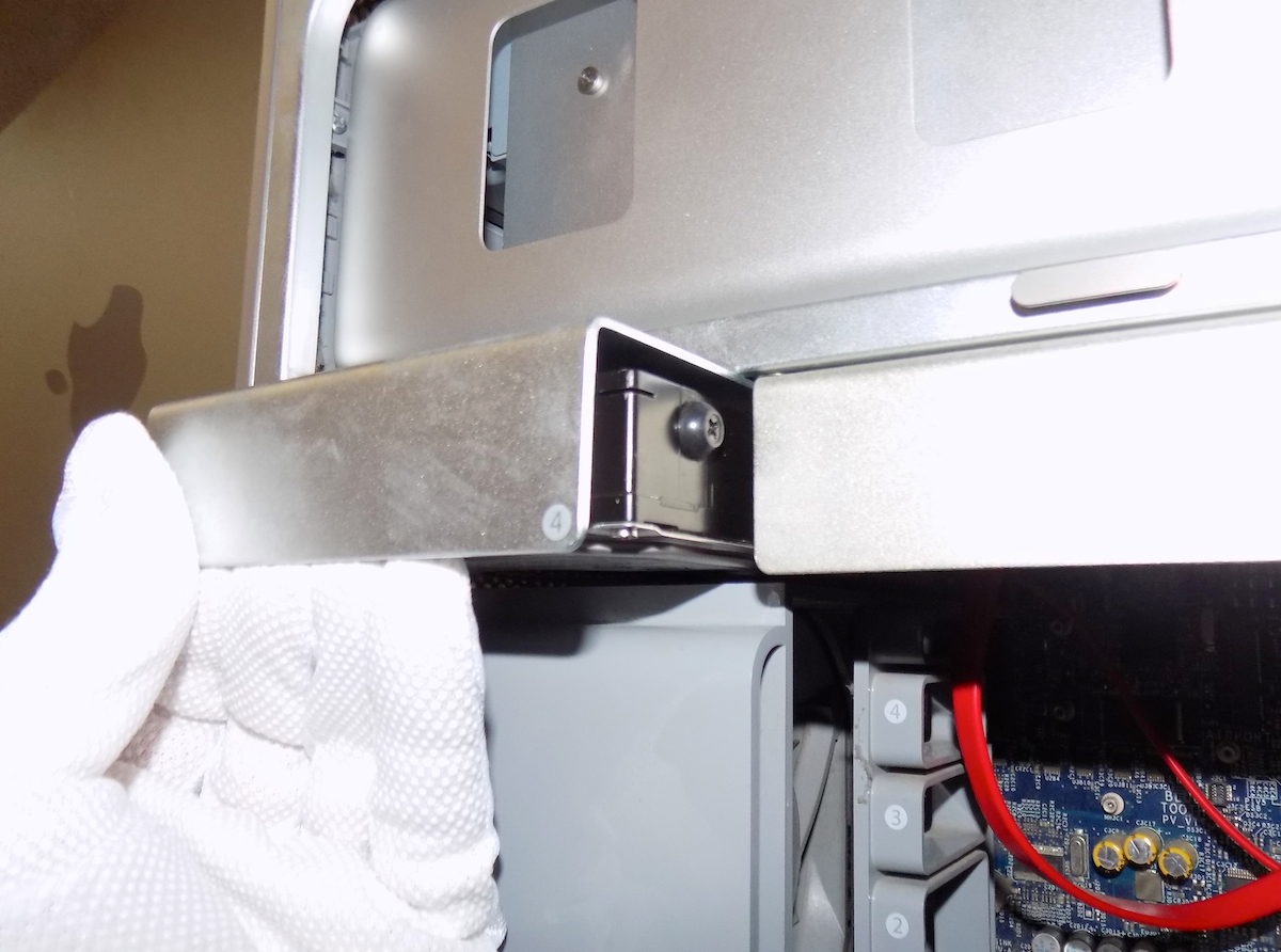
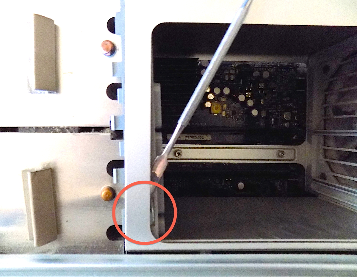
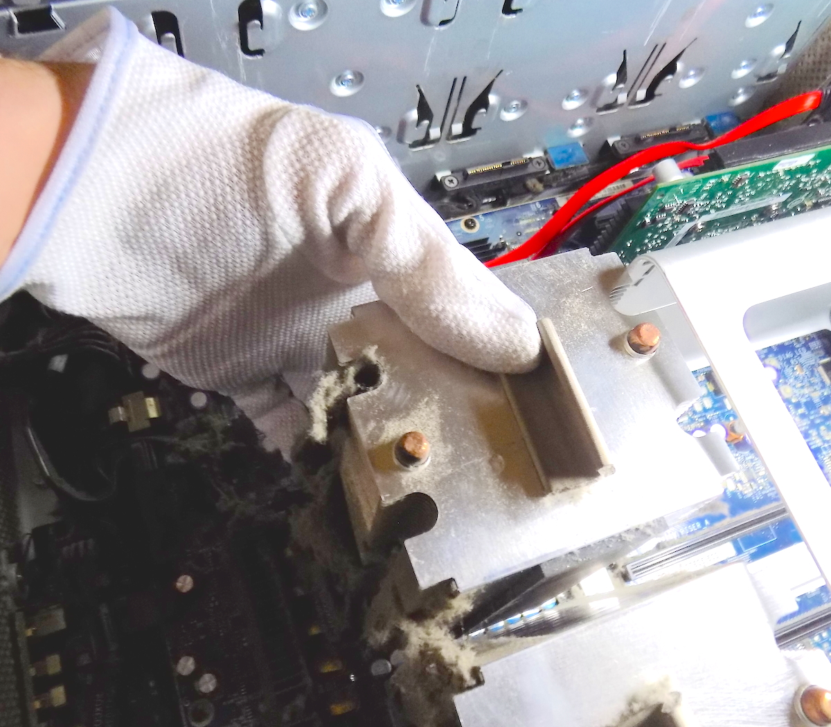
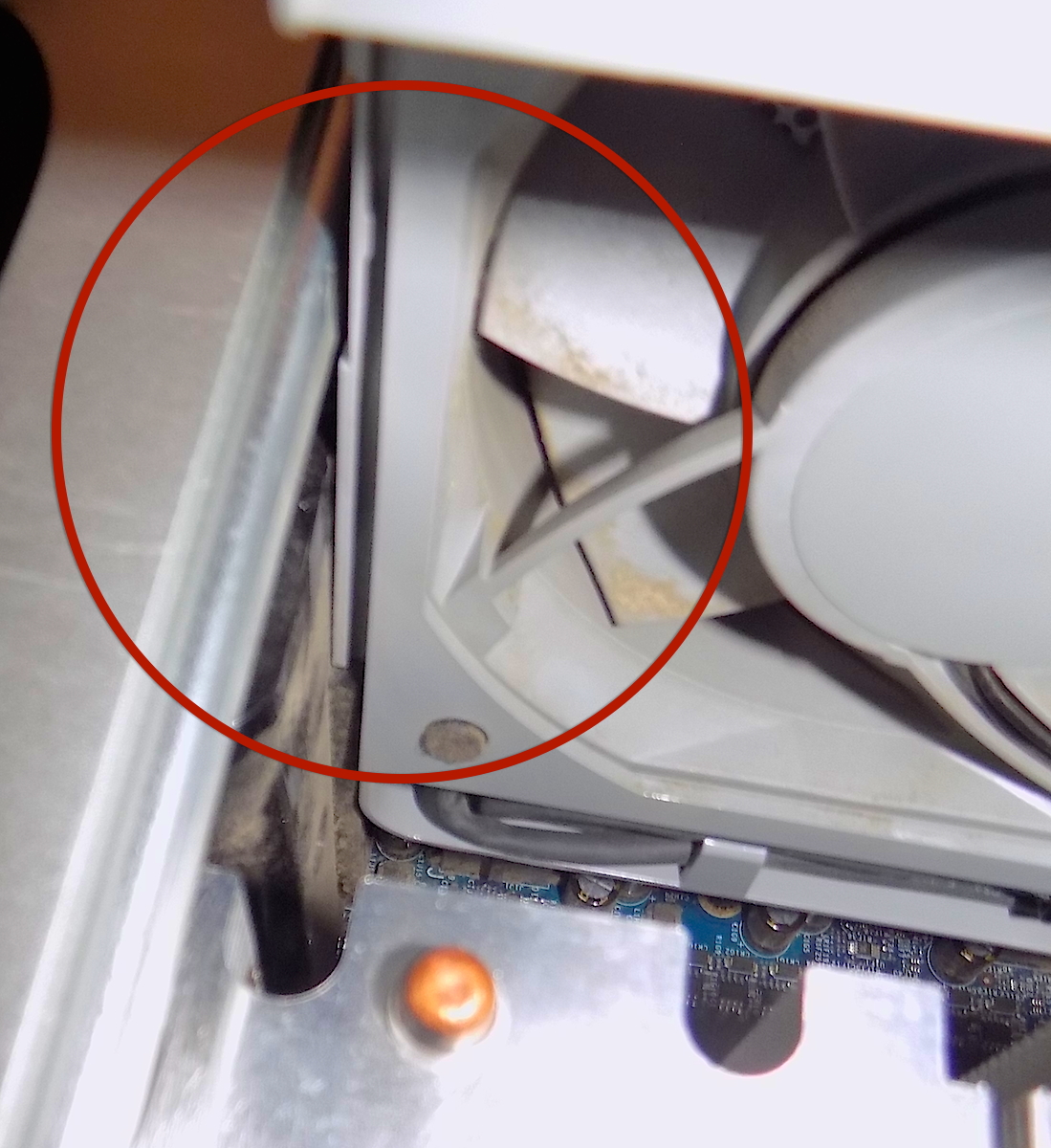
There is one screw holding the fan assembly in place. The screw is located on the top right of the fan assembly, in the hard drive 2 bay. Pictured below, marked by the red circle. There is a connector on the bottom of the fan assembly. It is a particular tight connector. The fan assembly has a rail that it slides into. The assembly must be lift straight up, sliding along the rail.
CAUTION: As always, take your time. The fan assembly should be pulled straight out, by grasping both ends of the assembly. This was the toughest piece for me to remove.

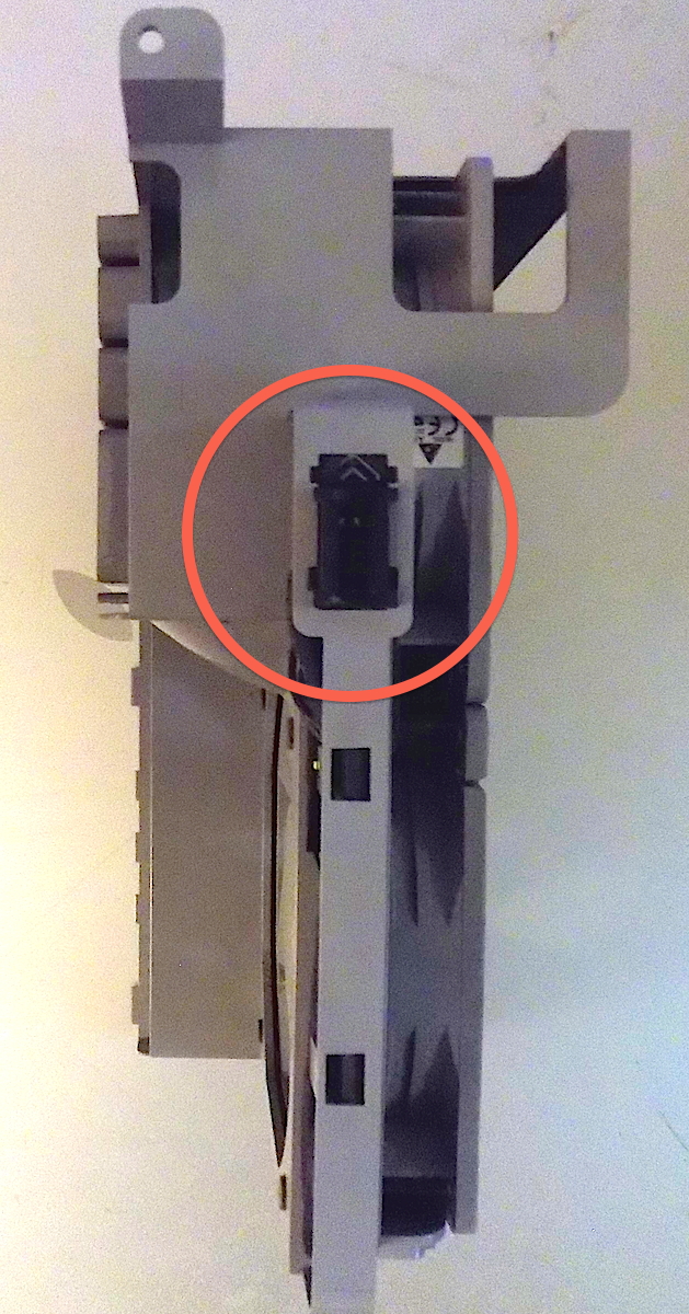
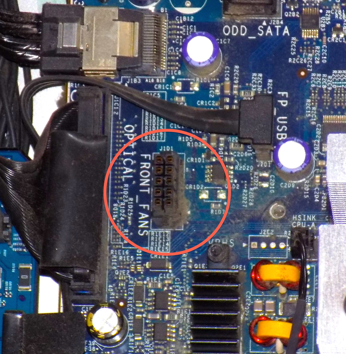
The above two pictures on the right shows where the connector is located on the fan assembly and the circuit board.
The left side of the heat sinks are now clear. The piece blocking the heat sink on the right needs to be removed. Don't remove the whole memory cage box, instead remove only the plastic piece blocking the heat sinks. This is a rounded square piece of plastic that snaps into the left portion of the memory cage.
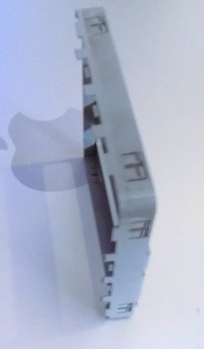
There are three tabs that lock the top portion of the plastic piece in place on the memory cage, two on top and on on the top side towards you (see picture of the removed plastic piece below, to reference the location of the tabs. Slip a flat metal spudger along the corners to separate the connection (Some suggest using a plastic credit card, but I find that using spudger to much easier). While the spudger is in place, push the plastic piece to the right. Don't force it. Take your time. Move along each tab, push the plastic piece slightly more with each tab. There is no need to lever the spudger, moving the spudger between the two pieces is sufficient, to separate the tab holding the two pieces together. In the above pictures, you can see part of the tab on the plastic piece as it is being pushed to the left. Remember, there are tabs on the top of the sides as well. Freeing these four tabs should allow the piece to be moved away from the heat sinks.
Now, we have access to the heat sinks and they can safely be removed. Before unscrewing the heat sink screws, disconnect the connecting wire to the motherboard. Disconnect both heat sinks wires, before beginning, so as to not forget and rip the wires from the heat sink, upon removal.
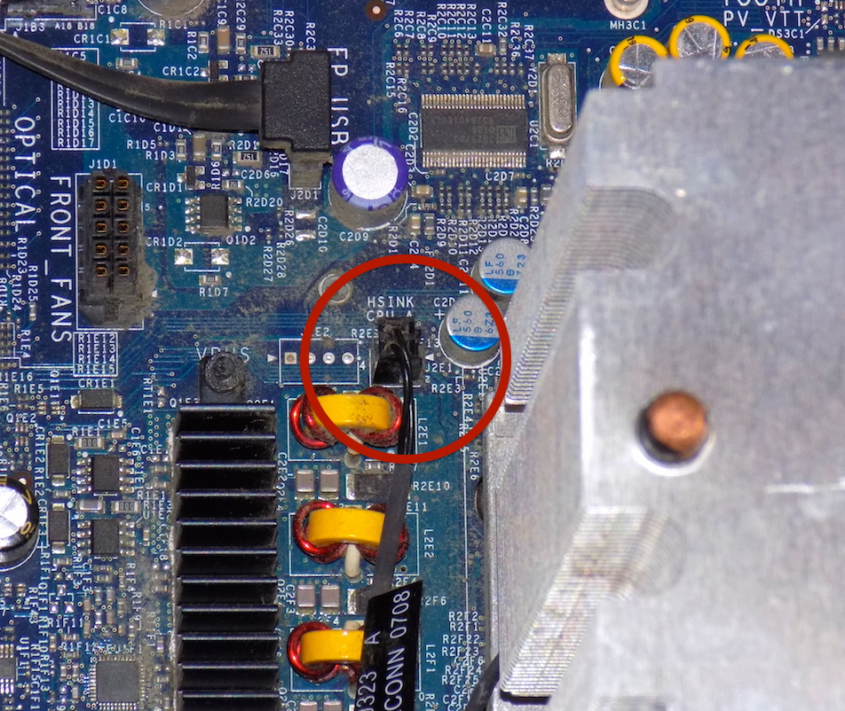
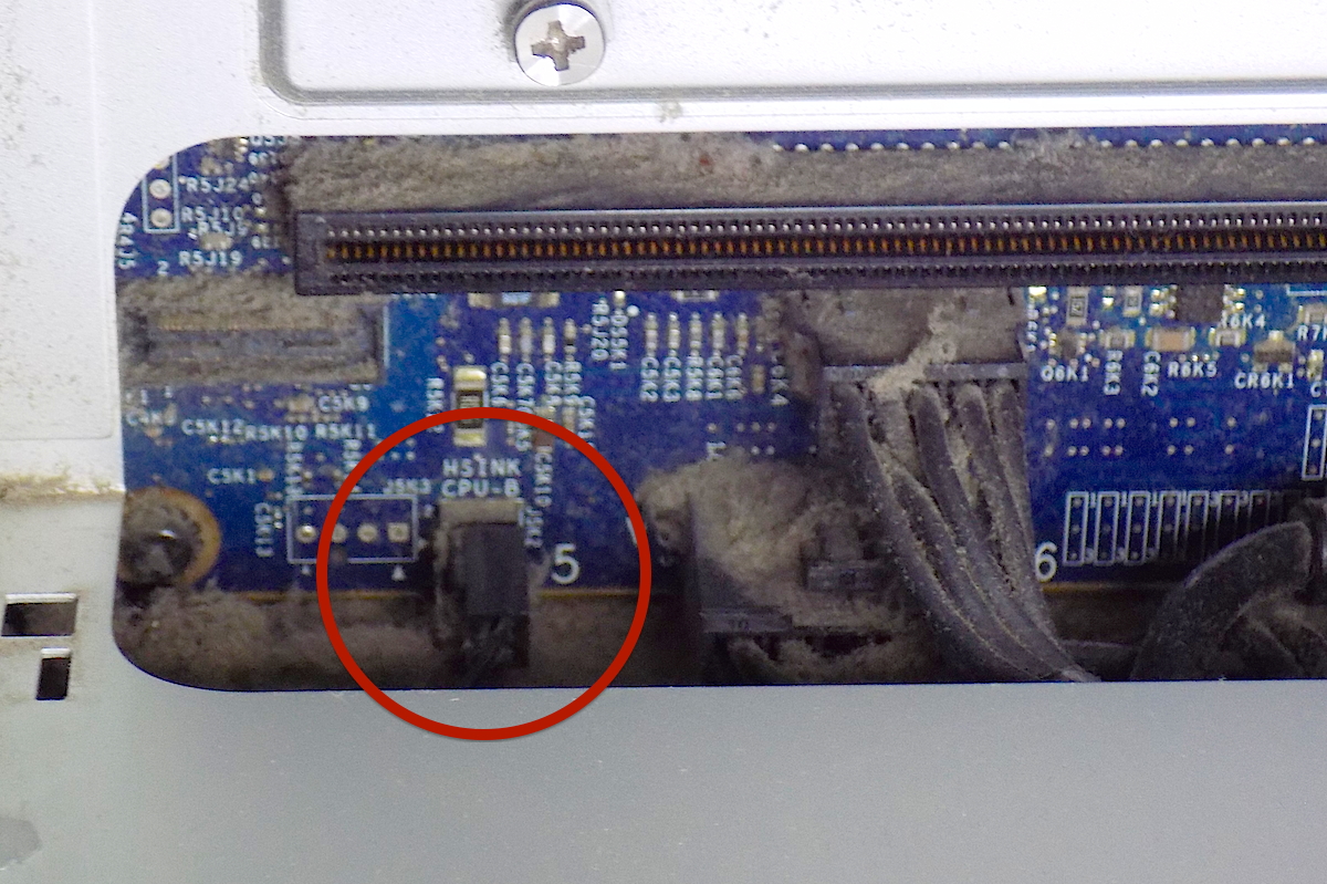
The first connector is next to the left of the first heat sink, labelled, "HSINK CPU-A". The second heat sink connector may be difficult to locate. It is under the memory cage, to the right of the heat sink and is labelled, "HSINK CPU-B".
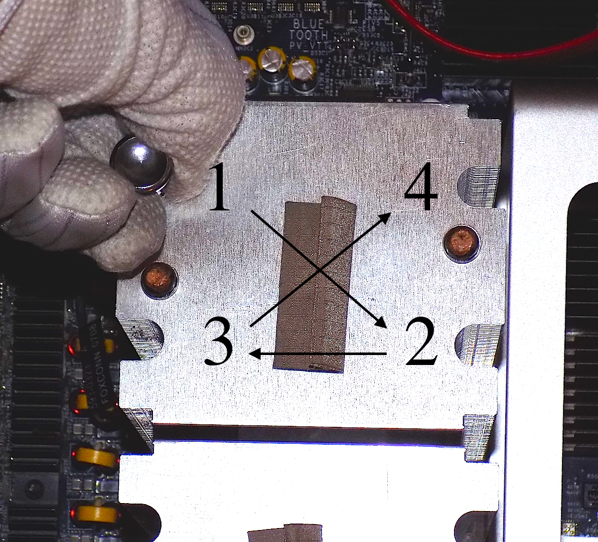
There are four Torx screws on each heat sink. It is recommended to unscrew the Torx screws in an 'X' pattern, crossing from side to side.
Since we haven't taken out the old CPUs yet, this is a good time to clean out any dust that has collected in the computer over the years. I would do this prior to taking out the old CPUs, to protect the contacts in the CPU holder. Clean dust from all the parts that have been removed, the fan, heat sinks and anywhere dust can be found. Use compressed air that is safe for electronics and plastic.
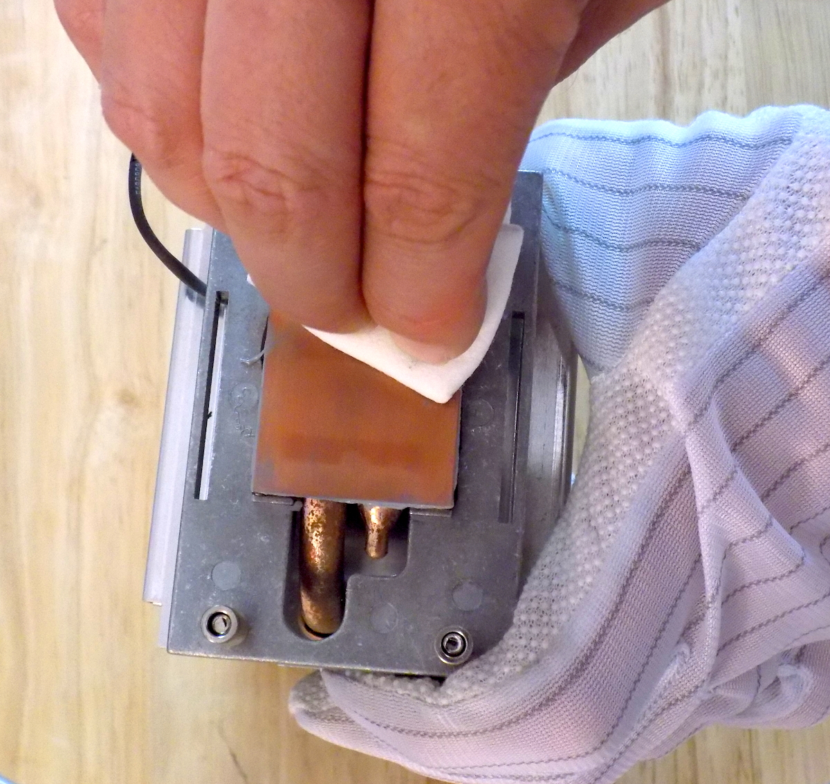
Before applying the thermal grease, the old thermal grease needs to be removed from the heat sink. Put a few drops of the ArctiClean on the surface of the heat sink. Spread it around with a Q-tip and let it sit for a few minutes. With a lint free cloth, wipe away the old thermal grease. Repeat applying the ArticClean and wiping it off. Make two application of the removal solution on the second heat sink.
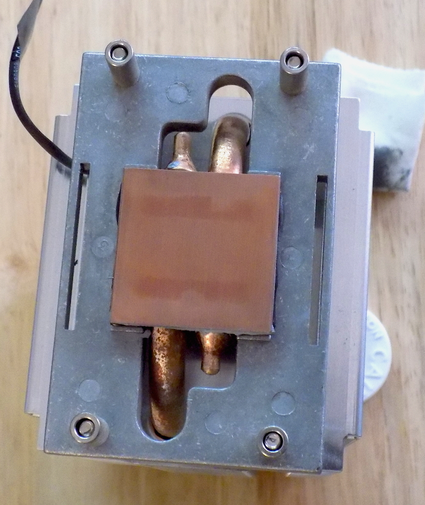
After both heat sinks are clean. Apply the thermal surface purifier in the same manor as above to both heat sinks.
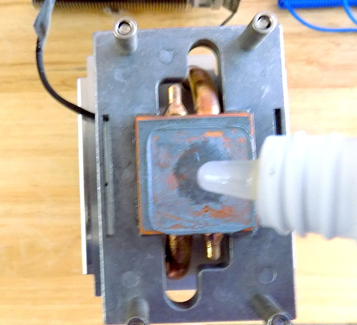
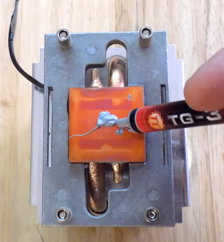
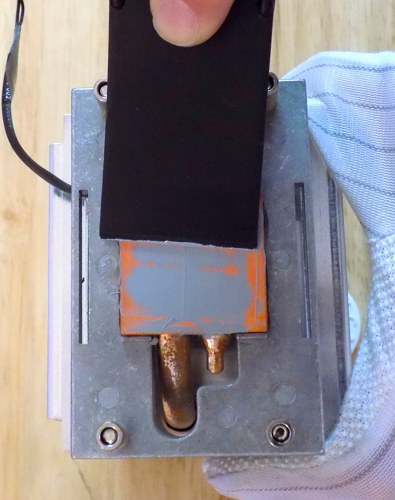
Now we are ready to embed a thin layer of thermal grease on the heat sink. Put a small dab of grease in the center of the heat sink. With a plastic putty knife or any piece of flat plastic, spread and press the grease into the surface of the heat sink. After the surface is sufficiently covered, wipe off the excess grease. The finished suface should be a dull grayish color.
The top surface of the new CPUs need to be prepared in the same manner, with a dab of thermal grease, speading and pressing in the grease with a plastic putty knife. If you are installing old CPUs that have thermal grease residue on them, remove the residue first with the ArctiClean remover.
CAUTION: It is very important to not touch the bottom of the CPUs. The CPUs should only be handled by the outer edges.
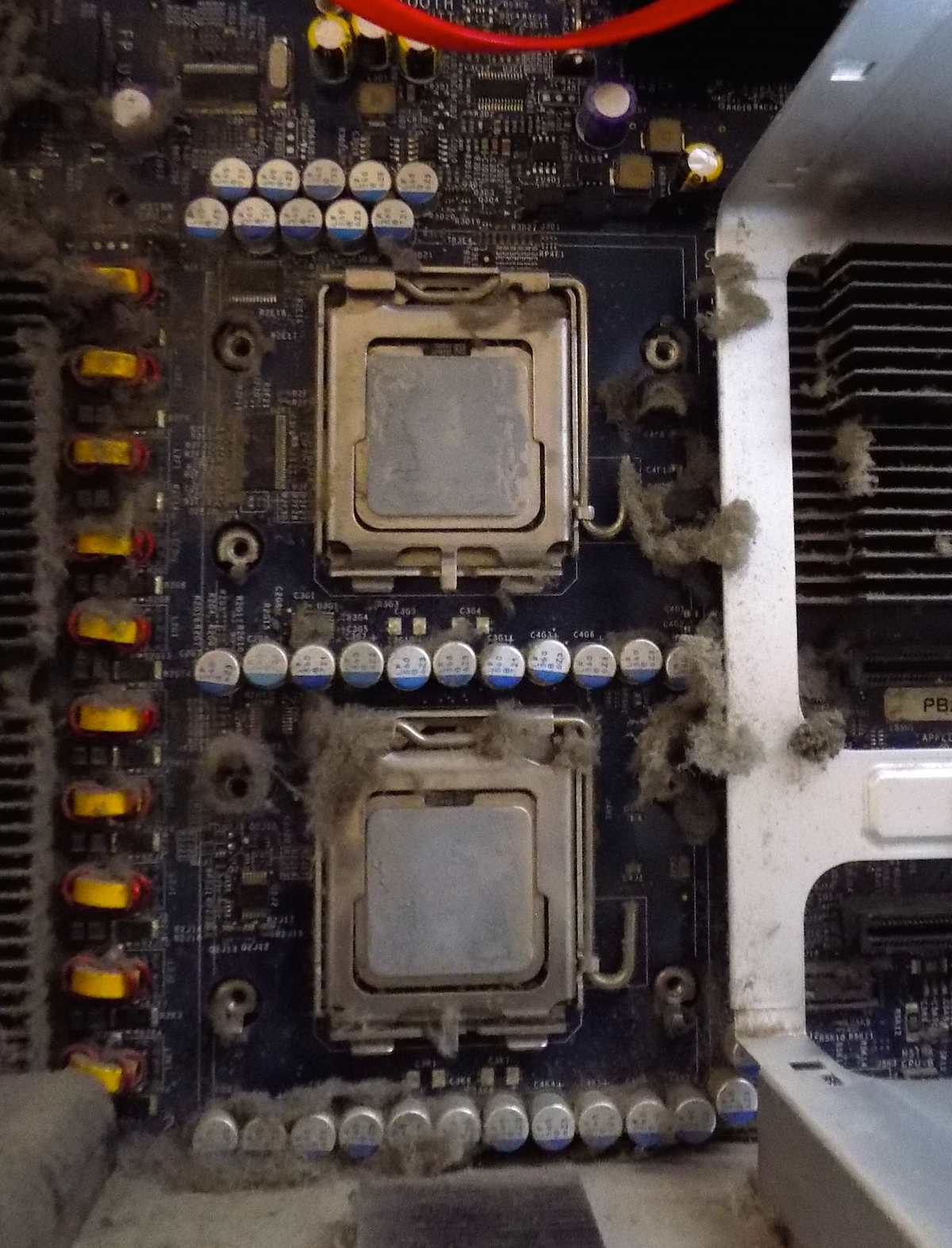
Now we are ready to put the new CPUs in the Mac Pro, the old CPUs can be removed. I leave the old CPUs in place as long as possible to keep the CPU holders as clean as possible. To open the locking door on the CPU holder, press down on the 'U' shaped end of the locking bar and swing it to the right to get it past to locking tab, as you bring it all the way up. The arm should be swung up as far as it will go, as it will release the door on the CPU holder. The door swings on a hinge downwards. Lift the door with a finger and swing it downwards.
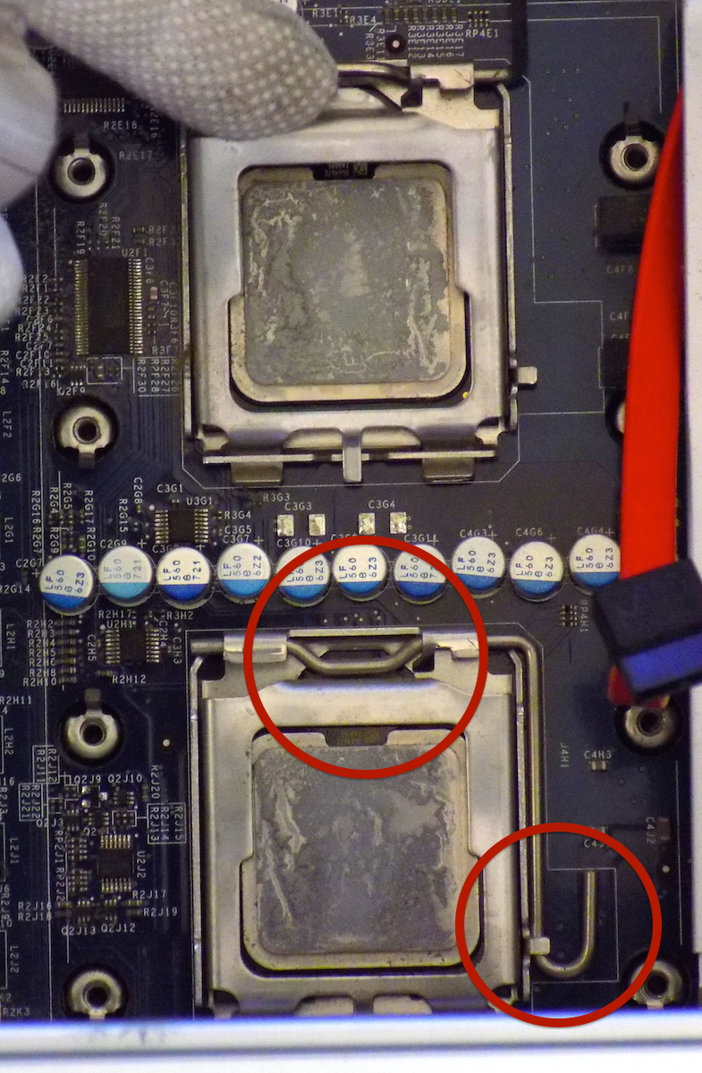
In the above image of the CPUs, the top CPU has been unlocked and the bottom CPU is still locked. The lower red circle on the right marks where the 'U' bar is located, as well as the locking tab. As the bar is swung upwards, it rotates the clamping bar away from the CPU holder door. Once the CPU door is unlocked, it can be opened downwards. Carefully remove the old CPU, avoilding to touch the bottom of the holder.
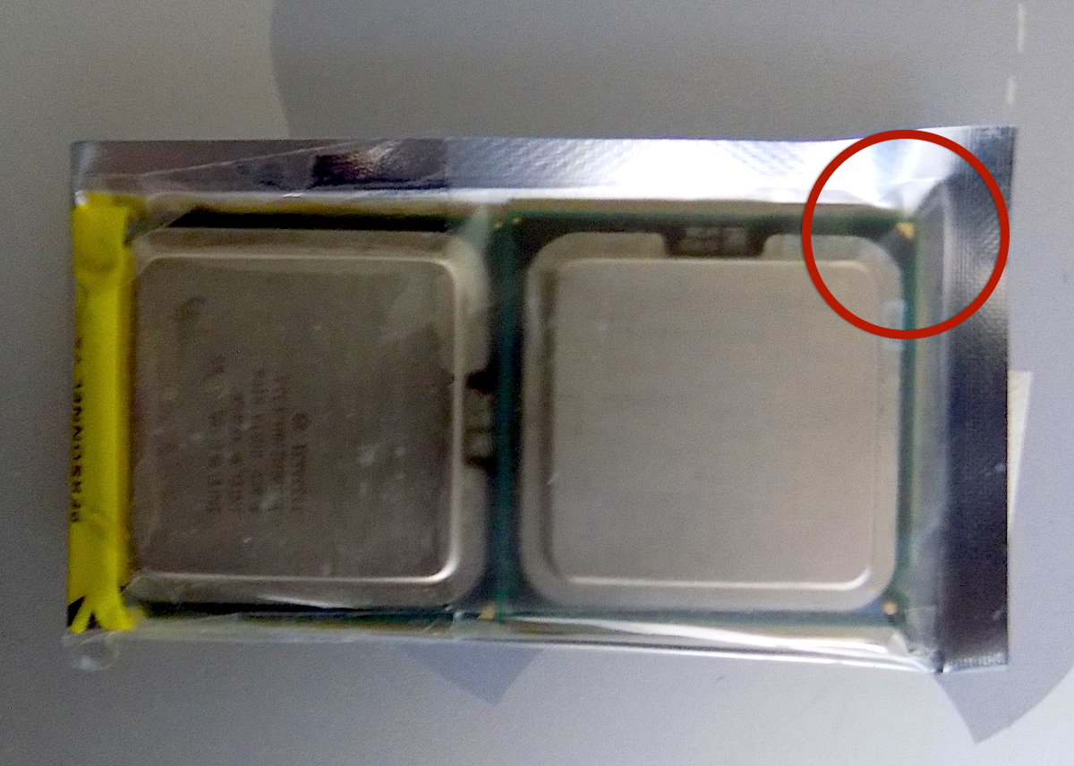
On the topside of the CPU in the top-right corner, there is a triangle in a corner. Use this triangle to orient the CPU correctly in the holder on athe motherboard. The triangle should be in the top-right. Place the new CPU into the holder, again avoid touching the bottom of the CPU or the holder, with the triangle in the top right. Always, hold the CPU on its sides. Swing the door closed and lock it down with the arm locked into the holder. Repeat this with the second CPU.
All that is needed is a line of thermal grease accross the top of the each CPU. It is easiest to start with last heat sink removed. When positioning this heat sink, thread the wire through to the memory cage. Position the heat sink screws over the screw holes and lower the heat sink into place. Tighten the screws in the same 'X' pattern that was used to remove the heat sinks. After the heat sink is secured, plug in the heat sink wire. Repeat this with the other heat sink.
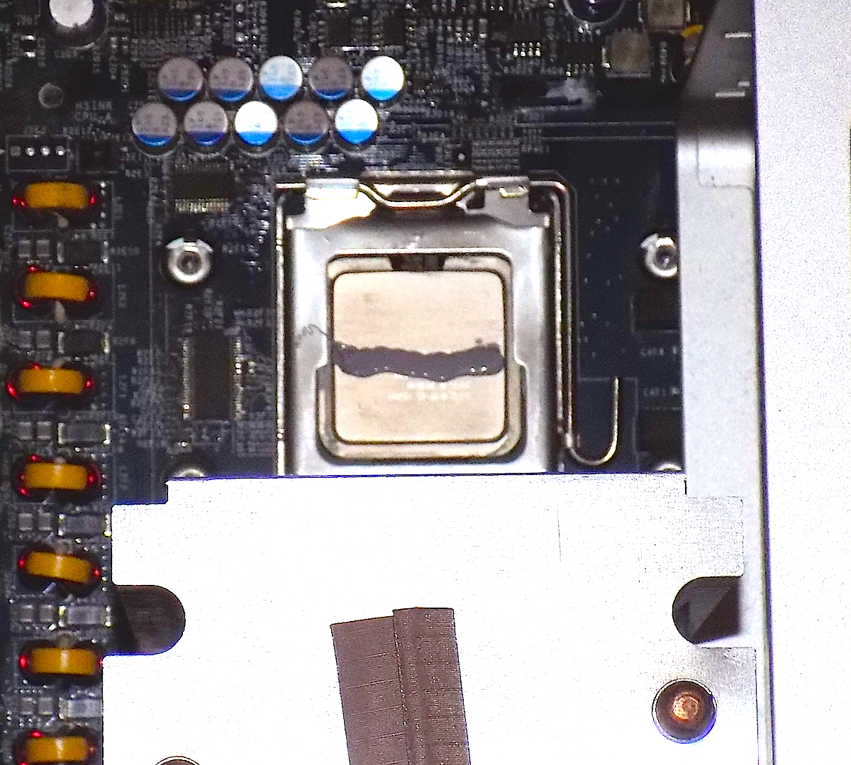
The picture aboves shows the first heat sink in place, after swapping the CPU. The CPU above it has a line of thermal grease across it.
Make sure to plug the heat sink wires back onto the motherboard
In the reverse order, reinstall each of the removed parts.
Place the bottom of the divider in place and then snap the top into place.
Make sure to slide the assembly into the rails and gently push the connector into place. The connectors will not line up, if you do not slide the fan in properly.
Move the memory cage slightly to the right and put the left of cover into place. Then move the memory cage back into place.
Screw in the bottom screws and then the two on the side. Now the memory board can be slid into place. Push the board edge with your thumbs until you feel it is securely in the card slot.
Testing Upgraded CPUs
 |
 |
Now, we are ready to try the newly upgraded Mac Pro. Looking at the CPU specifications in the Profiler, it doesn't recognize the name of the CPU, but it indicates that it is indeed a 3 GHz Quad Core CPU.
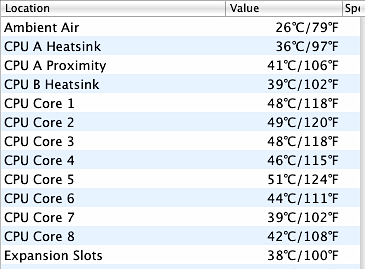
The greatest concern is that the CPUs can overheat, especially if something wasn't done quite right. The temperature of the cores should be monitored after their installation in the Mac Pro, to ensure that they won't fail from overheating.
Temperature Monitor can be used to report on the temperatures of various components of the computer, including the heat sinks and each of the eight CPU cores. According to CPU-World, the Intel Xeon X5365 shouldn't be operating at temperatures greater than 63°C. Ideally, a target temperature is somewhere between 45°C and 50°C. In the image of the Temperature Monitor dialog, there are the temperatures of each of the eight cores in Celcius and Farenheit.